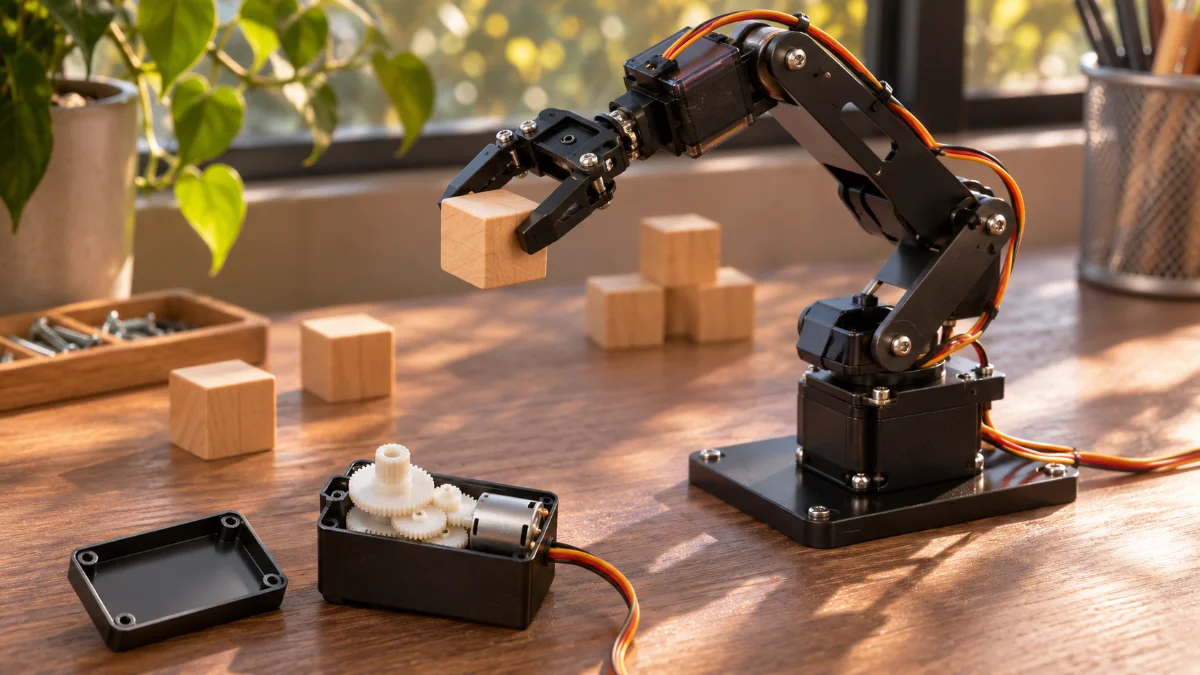
While a robot arm picks up an object and sets it down in exactly the right spot, the motor inside each joint keeps checking how far it has turned. The motor that stops when it reaches the commanded angle and returns to place when pushed away is the servo motor.
Put simply, a servo motor is ‘a motor with a built-in sensor that measures position and a circuit that makes decisions, so it holds a commanded position on its own.’ Its roots go back to a ship steering device designed in 1859 by the French engineer Joseph Farcot.
This article looks in turn at what a servo motor is and where it came from, the feedback principle that compares command with reality, the pulse signals that drive hobby servos, and how it differs from the stepper motor it is so often compared with.
A Servo Motor Turns While Comparing Command and Reality
1. What Is a Servo Motor?
An ordinary motor turns when power is on and stops when it is cut. It has no idea how far it turned in between. A servo motor adds a sensor that measures ‘where am I now’ and a circuit that makes decisions, so it stops at a set position and holds it there.
(1) A name that means a motor that obeys
In 1873 Farcot published a book titled “Le servo-moteur ou moteur asservi.” The French word asservi means ‘made to follow something else,’ so the very name captures a motor that faithfully follows commands.
(2) A steam device that turned a warship’s rudder
Farcot’s 1859 design used the actual position of the rudder to regulate how much steam went to the piston. Thanks to it, a single helmsman could steer a giant warship with a rudder weighing several tons using just one wheel. The principle of feeding back the position to correct the motion was already at work, which is why Farcot is counted among the pioneers of controlling machines through feedback.
(3) Servo motors today
Today most servo motors are electric motors fitted with sensors and electronic circuits. They are used wherever ‘exactly that position’ matters: industrial robot joints, machine tools, camera gimbals, the rudders of radio-controlled models, and even the small robot arms students build.
2. The Feedback Principle: Comparing Command and Reality
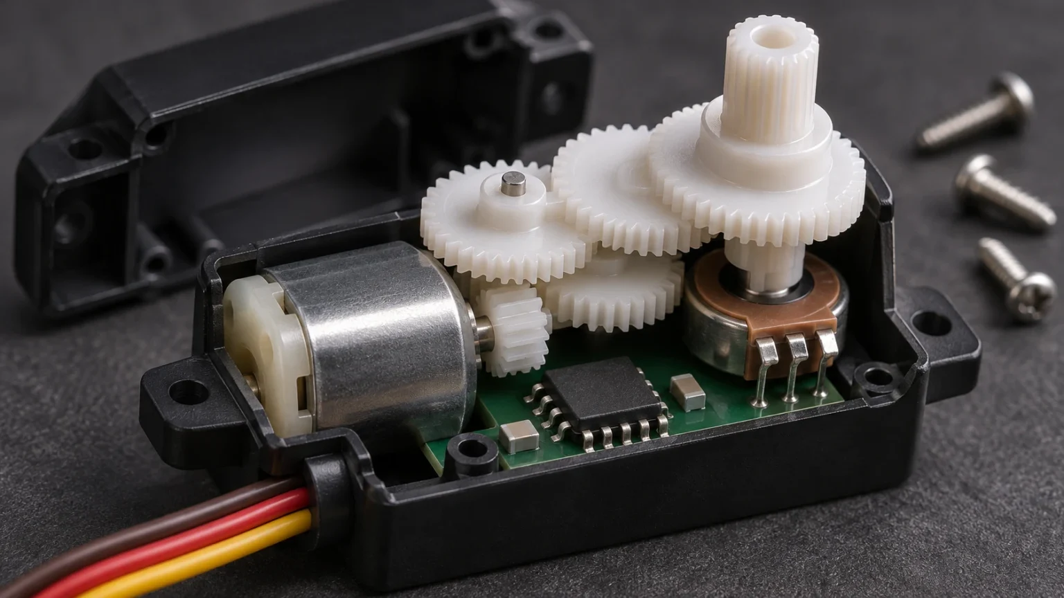
Open a servo motor’s case and you will find a small motor, a multi-stage reduction gear train, a position sensor connected to the output shaft, and a control circuit. Together these parts form a single loop that repeats the same task without rest.
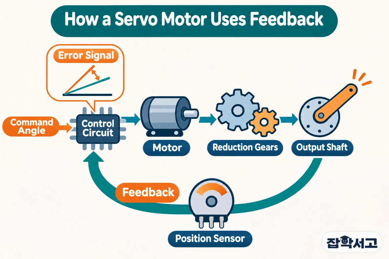
- Closed-loop control: a method that measures the result again, compares it with the command, and uses the difference to decide the next action.
- Error signal: the difference between the commanded position and the actual position. The control circuit reads this signal to decide which way and how far to turn the motor.
- Potentiometer: a sensor whose resistance changes as the shaft turns; in hobby servos it measures the angle of the output shaft.
- Encoder: a sensor that converts rotation into pulses or digital values; industrial servos use it to measure position more precisely.
- Reduction gear: it slows the motor’s fast rotation while increasing its force, then passes it to the output shaft.
The key is that ‘command’ and ‘reality’ are compared continuously. Push the output shaft lightly by hand and the sensor notices the mismatch, so the motor pushes back to return to its place. Methods such as proportional-integral-derivative control are often used to decide how quickly and smoothly that difference is reduced.
3. Hobby Servos That Express Angles Through Pulse Width
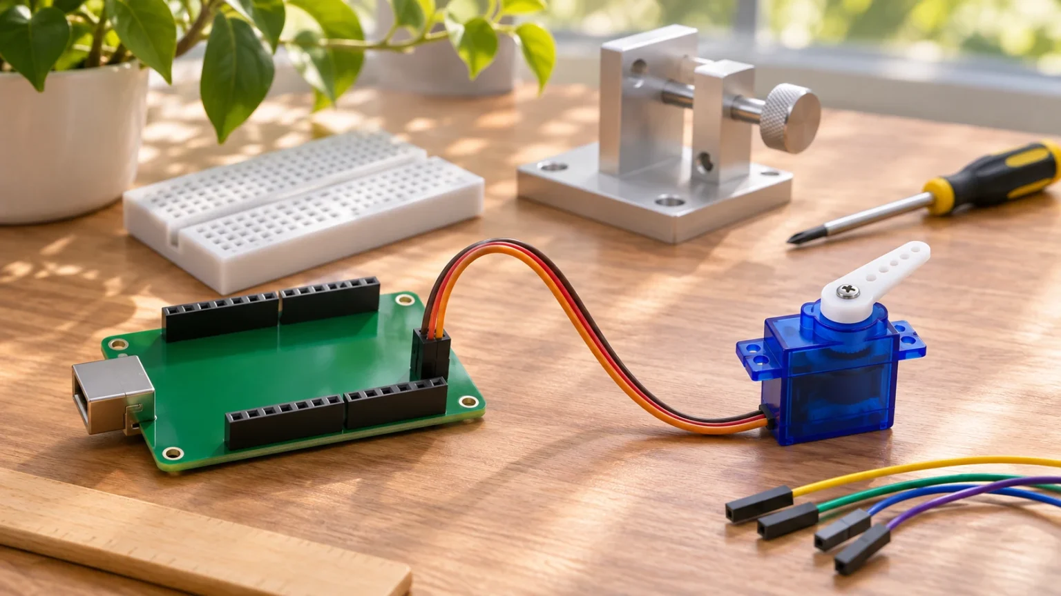
Hobby servos driven by small boards such as Arduino are the easiest place to see the servo principle up close. Carrying on the method used in radio-controlled models, they receive commands as very simple electrical pulses. Because a few wires and a short piece of code are enough to change the angle, they are widely used in robotics education too.
(1) Three wires
A hobby servo usually has three wires. Two are power and ground, and the third carries the command signal. A 4.8 V supply is known as the standard, and some products use 6 V or other voltages.
(2) A pulse every 20 milliseconds
Commands are sent as a pulse-width modulation (PWM) signal. A pulse arrives 50 times a second, that is, once every 20 milliseconds, and the length of time the pulse stays on represents the target angle. The range is usually 1.0 to 2.0 milliseconds, with 1.5 milliseconds as the center position. For example, a servo that moves up to 90 degrees goes to 0 degrees with a 1.0-millisecond pulse and to 90 degrees with a 2.0-millisecond pulse. The range of motion is generally between 90 and 180 degrees depending on the product.
(3) Servos that keep turning
There are also continuous-rotation servos made to drive wheels. In that case the pulse width represents the direction and speed of rotation rather than an angle, and 1.5 milliseconds becomes the stop signal.
4. How Is It Different from a Stepper Motor?
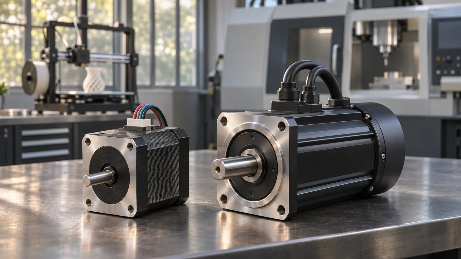
The motor most often compared with the servo is the stepper motor. Both are used to set positions, but the way they know where they are is fundamentally different. Even for the same job, the motor you choose changes how a machine copes with the unexpected.
(1) How position is known
A stepper motor turns by dividing one revolution into small steps. A common model moves 1.8 degrees per step, or 200 steps per revolution. It is generally an open-loop system that simply calculates position from the number of steps sent, without checking again with a sensor. A servo motor, by contrast, is a closed-loop system that measures the actual position with a sensor.
(2) When the load changes
An open-loop stepper motor can miss steps when an unexpected load is applied, and it cannot tell on its own that it has missed them. In a servo motor, however far it is pushed away is immediately registered as error, so it turns back and corrects its position.
(3) Which to choose
Stepper motors are simple to set up and tune and have strong holding torque at each step, which makes them a good fit for machines with steady loads such as 3D printers. Servo motors are mainly used in robot joints, where the load changes constantly and a lost position can quickly lead to an accident. These days there are also stepper motors fitted with encoders that combine the strengths of both.
Not stopping at turning as told, but checking to the very end whether it has truly reached that spot: that habit is the secret behind a servo motor’s precision.
Recommended reading